*Corresponding Author:
Trenkin AA,
Russian Federal Nuclear Center-All-Russian Research Institute of Experimental Physics, 37 Mira Ave., Sarov, 607190, Russia
E-mail: alexey.trenkin@gmail.com
Abstract
This paper presents studies of different stages of a discharge in the air of atmospheric pressure as well as the nature of the electrodes damage. The gaps between the tip and the plane electrodes were used. During the research, a corona discharge, a diffusive discharge formed by a wide streamer, a diffusive discharge with bright spots on a flat electrode, and a spark discharge in a gap were registered. It was established that these stages were formed sequentially. The implementation of one, two, three or all of the above stages was ensured by changing the length of the gap, the shape of the tip electrode as well as the front, duration, and amplitude of the voltage pulse. Under conditions of a nanosecond diffusive discharge without bright spots on the plane electrode, the damage of a plane cathode (made of aluminum foil) was not observed. It is shown that the formation of bright spots on a flat electrode and a spark stage, regardless of the polarity of the tip and the shape of its surface, occurred in the microstructuring (filamentation) mode of the discharge; the areas of its erosive action on the plane electrode represented an accumulation of a large number of microcraters.
Keywords
Electrode erosion; Streamer; Diffuse discharge; Spark discharge; Microstructure
Introduction
A pulsed breakdown of the air of atmospheric pressure in homogeneous electric field as well a sat the use of electrodes with a small curvature radius was studied in a large number of works, for example, see the monographs [1-6] and references in them. The diffusive discharges [5-9] or diffusive discharges with spark leaders [10-12] are formed at nanosecond voltage pulses and comparatively large gaps (“pin-to-plane”). As a rule, runaway electron beams and X-rays are recorded at such discharges and negative polarity of the electrode with a small curvature radius (pin electrode) [6-8,13-18]. Besides, the erosion traces emerge on the plane electrode, when the bright spots appear on it [5]. A spark discharge and different damages of the electrode surface are observed at increase of a voltage pulse duration and interelectrode gap reduction [19-25]. So, it was shown in [19-21,23] that the prints (autographs) of the spark discharges on the surface of a plane electrode represent a cluster of a large number of microcraters. At the same time, a discharge microstructure (a spark channel represents a sheaf of a large number of microchannels with the diameter of 10-30 μm) was recorded in the interelectrode gap by a shadow photography method [21,24,25]. Note that this method was also used in studies to study the contraction of a discharge in atmospheric pressure air [26,27]. However, the integrate study of different stages of a discharge and their influence on the electrode state at the wide variety of voltage pulse parameters and the usage of different methods of a discharge plasma registration in a single pulse mode has not been performed before.
The current work is aimed to study the influence of the experimental conditions (the gap length, the front, duration, and the amplitude of a voltage pulse, the shape of a pin electrode) in the pin-to-plane gap on a plane electrode damage, and on different stages of a discharge in the air of atmospheric pressure.
Materials and Methods
Three high voltage setups were used in the research. The scheme of the experimental setup №1 is illustrated in Figure 1.
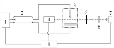
Figure 1: The scheme of the experimental setup №1. 1-high-voltage generator, 2-cable line, 3-discharge gap, 4-probing signal source (laser), 5-objective, 6-light filters, 7-streak camera, 8-synchronizer.
The setup itself and the realized method of the shadow photography are described in details in [21]. The main idea of the experiments was the following. A pulse with the amplitude of 25 kV and the front duration of about 7 ns on the level of 0.1-0.9 was supplied to the discharge gap from the high-voltage generator by means of a cable line. The generators with positive and negative pulse polarities were used. The voltage and current were recorded at the output of the high-voltage generators. The electrode system had the “pin-to- plane” geometry. Several axisymmetric pin electrodes were used. They differed by surface shapes and are described in details in [25]. Two electrodes were used in most of the experiments. The first one (further in the text, electrode №1) had the length of 19 mm, diameter of 14 mm, apex angle of 36°, and the curvature radius of 0.15 mm. The second one (further in the text, electrode №2) had the length of 40mm, diameter of 10 mm, apex angle of 14°, and the curvature radius of 0.1 mm. Both electrodes were made of stainless steel. The plane electrode was made of aluminum alloy; its working section was close to the ball segment in form with the diameter of 4.5 cm and thickness of 1.5 cm.
Two types of a discharge according to the gap were realized. Those are a spark discharge and a diffusive discharge with the gaps of 1.5 mm and 18 mm, respectively.
In the first case, there was an oscillation process with an exponential damping of current amplitudes and voltage after the gap breakdown in the discharge circuit. The oscillation period was 0.6 μs, the current amplitude and its damping time were 1 kA and 1.2 μs, respectively.
In the second case, the voltage at the generator output decreased exponentially after the gap breakdown and its polarity did not change. The time of the voltage drop was about 0.5 μs. The discharge current reached 30 A.
Two characteristic time moments were distinguished on the waveforms in both types of the discharges: a voltage appearance on the discharge gap and a breakdown. Time delay between them differed from pulse to pulse. The mean value of the delay between them was 4ns. The moment of the current rise and the voltage drop was considered for the breakdown moment tbd.
The shadow photography method was used in the experiments for the recording of a spatial discharge structure. The discharge translucence was performed by a solid-state laser with a wavelength of 532 nm and a pulse FWHM of 6 ns. The image of a shadow pattern allocated in the area of a discharge gap was made by means of an objective with a focal distance of 23 cm on the photocathode of an electron-optical recorder. The magnification factor was equal to ten. The frame exposure was defined by the length of a laser pulse.
The laser was not used in the photography experiments of the natural discharge glow. The frame exposure of the electron-optical recorder was 40 ns. A part of the exposure time advanced the start of the discharge formation at the photography of early stages of the discharge (for the time of less than 40 ns).The visualization of different stages of the discharge process was performed by a moment shift of a laser firing and a streak camera triggering relative to the breakdown moment. The shooting was in a single frame mode (one frame per pulse). The resolution of the optical system with was 5 μm per three pixels.
Time reference of the frames was performed in the following way. For the shadow photography, the time, characterizing the frame, was counted out from the breakdown moment and corresponded to the beginning of the frame. For the images of the natural discharge glow, the time was counted out from the moment of the voltage supply to the discharge gap and corresponded to the end of the frame.
In a series of experiments, besides a high-speed shooting, there was also a shooting of an integral glow of a discharge in a close angle by a digital camera.
A gas-discharge chamber with a short coaxial line and high-voltage generators HV with a wave resistance of 75 Ω were used at the second experimental setup. The generators formed voltage pulses of positive or negative polarities. The experimental scheme and waveforms of the voltage pulses are illustrated in Figure 2.
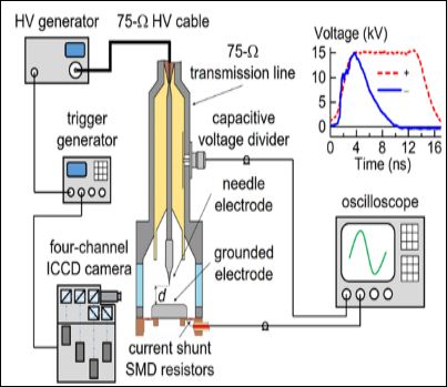
Figure 2: The scheme of the experimental setup №2 for the discharge study by means of a four-channel ICCD camera.
The generator GIN-100-01 (U=5-25 kV, τ0.1–0.7≈0.7 ns, τ0.5≈4 ns) had a negative polarity, and the generator GIN-50-1 (U=5-25 kV, τ0.2–0.9≈2.2 ns, τ0.5≈13 ns) had a positive polarity [28]. The voltage pulses were transmitted along a high-voltage cable to the input of a coaxial line. The generators triggering was performed by means of a pulse generator BNC-565. The voltage on the gap was measured by a capacitive voltage divider. The time of a voltage wave front distribution from the divider to the gap was 0.38 ns. A four-channel ICCD camera HSFC-PRO (the minimum exposure time was 3 ns) recorded the light from the discharge plasma. A quartz window was used for output radiation. In addition, the discharge glow was photographed with a digital camera. A high-voltage electrode was made of a sewing needle of 5mm length with the basis diameter of 1mm and the curvature radius of 75 μm. A grounded electrode was a plane one. It also served as a current-collecting part of a shunt made of chip-resistors. The distance d between the electrodes was 8.5 mm. Signals from the capacitive voltage divider and current shunt, and also the triggering signal of the first channel of the ICCD camera were delivered to the oscilloscope Tektronix TDS 3054 B (500 MHz, 5 GS/s). The gas-discharge chamber was exhausted and then filled with air up to the pressure of 100 kPa.
The third experimental setup was similar to the setup №2. However, the nitrogen circulation through the gap with the velocity of 5 l/min was provided there. It allowed removing metallic vapor of the electrodes, which appeared in a gap after the spots had been formed on the electrodes and a spark had been generated [29]. The generator NPG-18/3500N [30] was used in the experiments. It formed the voltage pulses of a negative polarity with the amplitude of an incident wave in the transmission line from 5 to 20 kV, with a front duration of τ0.1–0.9≈3 ns and a pulse FWHM of τ0.5≈ 6 ns. A steel conic cathode was used as a high-voltage electrode. Its length was 25 mm, the apex angle was 60°, and the curvature radius was 100 μm. A plane grounded anode was made of Al foil of 10 μm thickness. The second plane polished electrode was made of stainless steel and used in a series of experiments with large gaps. Its surface was covered by graphite (carbon-black of a candle) of 7-8 μm thickness. A gap d was changed from 2 to 10 mm. A capacitive divider measured the voltage at the discharge gap; discharge current was measured by a shunt connecting the anode with a camera enclosure. An optical microscope defined the properties of a plane electrode surface after they had been treated by a discharge in different modes on the setups №2 and №3.
We should note that in these experiments the gap resistance was changed at the diffusive discharge, and it could be more or less than the wave resistance of the generator. Thus, the reflected pulses arrived to the gap. The gap resistance decreased at the spark discharge and a similar amplitude of the generator voltage pulse. The amplitude of the discharge current and the number of reflected pulses increased; that resulted in the additional damage of the plane electrode. The best matching of a generator and a diffusive discharge on the facility №3 was reached at the gaps of 9 and 10 mm. Bright spots on the plane electrode were absent in the majority of pulses in this mode.
Results and Discussion
Spark discharge stage
The experimental results obtained on the setup №1 are provided below. The generator with alonger voltage pulse and its front (compared to the generators of the setups №2 and №3) was used in the study. The photos of the glow of the initial phase of the spark discharge in different time moments for a negative polarity of a pin electrode are illustrated in Figures 3.
The photos allow defining the following discharge dynamics. First, a diffusive channel, cathode spots, and anode spots appear. Then these glowing formations (from spots) are propagated in the direction to each other, and a bright glowing channel is created. The diameters of diffusive and bright glowing channels are 1 mm and 0.3 mm, respectively. The spots dimensions are from 20 to 50 μm. The diffusive channel, cathode, and anode spots were formed in the intervals from 0 through 5 ns after the voltage supply to a discharge gap. At the same time, the bright spots were visible only on the pin cathode for 1ns after the voltage supply to the discharge gap (Figure 3(a)). On the photo, there were at least 4 spots, and their number was changing from pulse to pulse. The bright spots were recorded on the plane anode in 1–3 ns after the voltage had appeared (Figure 3(b)). Apparently, this could be considered as a pre-breakdownstage.Then, the propagation of the bright glowing channel (spark leader) from spots was observed in the interval from 5 through 15ns, and the gap was closed (Figure 3(c)). The velocity of the brightly glowing channel propagationfrom the cathode was about 105 m/s.
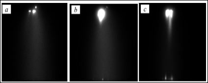
Figure 3: Frames of the spark discharge (a), (b), (c) natural glow in different time moments relative to the voltage supply to the discharge gap [(a)-1ns, (b)-3ns, (c)-6ns] for the electrode №1(upwards). The interelectrode gap is 1.5 mm.
Similar results in the dynamics of a discharge glow were obtained in the case with a pin anode [25]. The shadowgraphs of a spark discharge in different time moments for a negative polarity of a pin electrode are presented in Figure 4.
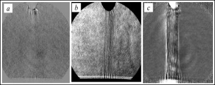
Figure 4: Shadowgraphs of the spark discharge with the electrode №2 in different time moments relative to the breakdown start tbd: (a)-1 ns, (b)-12 ns, (c)-23 ns. Elec- trode-pin is upwards. Interelectrode gap is 1.5 mm.
We should note that tbd was changed from pulse to pulse, and the mean value of a delay between the voltage supply to the discharge gap and the breakdown was ≈4 ns. It is evident in the shadowgraphs that the discharge is being developed in the microchannel form; the channel represents a sheaf of a large number of microchannels. It should be noted that the microstructure was not visible on the frames of the natural glow of the spark discharge.
Immediately after the breakdown (Figure 4a), the plasma formations with the diameter from 20 to 50 μm are recorded on the shadowgraphs. They are developed from the pin electrode. A microstructuring channel closes the gap at 2 ns and has the near- cylinder form. When analyzing this photo, one should take into account that the laser pulse duration is 6 ns at FWHM.
The discharge current increases sharply and achieves the value of 1 kA during 10-15 ns after the breakdown. At the same time, the channel diameter is not practically changed up to 15-20 ns and is about 250 μm. All these indicate the intensive growth of the plasma conductivity in the microchannels during this period. A number of microchannels and their diameters are estimated by this time as 100 and 10-30 μm, respectively. The current density in the microchannels is 105-106 A/ cm2. Then an intensive radial expansion of a channel begins; a shock wave is formed on the boundary of the channel [21,24].
The shadowgraphs of a discharge channel are presented in Figure 5 in different time moments for a pin electrode of positive polarity.
It is evident that in this case a discharge is developing in a microchannel form. First, the microchannels are recorded near the pin electrode (Figure 5a), and then in the whole gap (Figures 5b and 5c). At the same time, there are the areas of connection with several nearby microchannels (Figure 5c) on the plane cathode. The dimensions of such areas are specified according to the shadowgraphs; and they are close to the cathode spot dimensions on the frames of glow. Apparently, they can be identified with them.
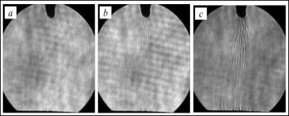
Figure 5: Shadowgraphs of the spark discharge at different time moments relative to the breakdown [(a)-2 ns, (b)-5 ns, (c)-8 ns] for the electrode № 2 (upwards). Interelec- trode gap is 1.5 mm.
The method of autographs was used to study the erosion influence of a spark discharge. In this case, a copper plane of 2 mm thickness and working surface of 50×20 mm2 was served as a plane electrode. The plane electrode was mirror-polished to obtain a discharge autograph. After that, one voltage pulse was supplied to the gap.
The area of a discharge influence was studied by a 3D optical profile meter [20]. The dimension of the influence area was about 160 μm. The results of the place visualization of the erosion area are provided in Figure 6a. It is evident that the indicated area represents a cluster of microcraters. A profile of a certain microcrater is presented in Figure 6b.
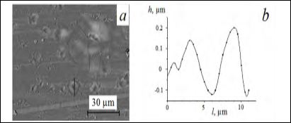
Figure 6: Image of the erosion area on the surface of a plane copper electrode (a) and a surface profilogram (b) along the way l, marked in Figure 6(a) by a black segment.
The microcraters represent hollows in the central area and half- spherical rollers on the periphery. The rollers width is from 2 to 5 μm for rather large microcraters, hollow diameters are from 2 to 4 μm, and their depth is from 0.1 to 0.4 μm. At the same time, the bottom of some microcraters has a plane form and even a hill in the central part, though some of the microcraters have a hollow of the cup form. There are also microcraters of 1 μm diameter and less in the autograph structure.
An integral photo of a diffusive discharge is shown in Figure 7. The discharge is formed with the electrode № 2 at the voltage pulse supply with a positive polarity. It is evident that bright spots are formed on the pin and plane electrodes. The time of the spots appearance is unknown as a high-speed photo shooting of the diffusive discharge was not carried out.
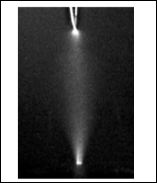
Figure 7: Integral photo of the diffusive discharge glow with the electrode № 2 (up- wards). Interelectrode gap is 18 mm.
The field-of-view of the diffusive discharge at the shadow photography was the same as for the spark discharge. That is why, only the area near the pin electrode was in the picture.
The shadowgraphs of the diffusive discharge for the electrode № 1 at different time moments relative to the breakdown are provided in Figure 8. A lot of microchannels issuing from the pin are recorded on the shadowgraphs since 20-30 ns (Figure 8a). Gradually, the microchannels are being developed inside the gap (Figure 8b). The boundaries of some discharge channels become evident approximately since 60 ns (Figure 8c). The channel structure of the discharge recorded in the shadowgraphs is well correlated with its integral images at the simultaneous shooting. But the microstructure was invisible in the frames of the integral glow of the diffusive discharge.
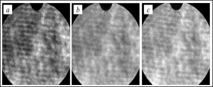
Figure 8: Shadow graphs of the diffusive discharge in different time moments relative to the breakdown [(a)–30 ns, (b)-44 ns, (c)-70 ns] for the electrode № 1 (upwards).
Pre-breakdown stage of a discharge
Studies of the luminosity from the gap in the pre-breakdown stage of the discharge in an in homogeneous electric field were carried out at the setup № 2 using an ICCD camera. First, there was a weak glow near a pin electrode. This glow is connected with a streamer formation. The streamer crossed only a part of the discharge gap during the time of the voltage pulse. It is known that this mode corresponds to the pulsed corona discharge and is realized at the decrease of the amplitude and voltage pulse duration, and at the increase of a gap [31,32]. The discharge photos and oscillograms in this mode at the positive polarity of the pin electrode are shown in Figures 9a and 9b.
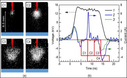
Figure 9: (a) Images of the streamer glow in the air of atmospheric pressure. (b)Voltage waveform (1), waveforms of the current (2) and displacement current (3) recorded by a current shunt. The streamer was late in crossing the gap during the time, when the voltage was being applied to the gap. The displacement current was calculated multi- plying dU/dt by the value of the capacitance of a gas-discharge gap Сgap. C1, C2, C3, C4 are the channel numbers of the ICCD camera. The width and location of the rectangles correspond to the exposure and switching moments of the ICCD camera channels.
As plasma does not touch the plane electrode, its surface is not damage the corona discharge. The current amplitudes through the gap did not exceed 10 A at the setup № 2 in such conditions. The current through a gap was conditioned by a conduction current through a streamer plasma in the area of its glow, and by a dynamic displacement current of a compressible capacitor between a streamer head and a plane electrode [33,34]. The dynamics of a streamer development was similar at the negative polarity of a pin electrode.
It should be also noted that the corona discharge consisting of cylindrical streamers that reach the plane electrode, can be easily realized by applying a positive polarity DC voltage to the electrode with a small radius of curvature [35]. However, in this mode at the voltage of tens of kilovolts, the average and pulse discharge currents are small. They do not exceed hundreds of microamperes and units of milliamperes in the air of atmospheric pressure. In this mode, the microcraters on the plane electrode were also not observed.
Stage of a diffusive discharge
The transition from the stage of a corona discharge to a diffusive one in the air of atmospheric pressure at the setup № 2 was observed at the growth of the voltage pulse amplitude. Besides, the mode could be realized without bright spots on the plane electrode and with them as well. According to the works [36,37], the gap closure is performed by a streamer in the inhomogeneous electrical field at the pin electrode with a small radius of the curvature. As a result, the diffusive discharge is formed. Besides, the streamer form depends on the generator voltage. The ball streamer is transformed into the cylindrical streamer of a smaller diameter; it closes the discharge gap at the comparatively small growth of the voltage pulse amplitude; see also [36,37]. The ball streamer (wide streamer) is shown in Figure 9.
The ball streamer crosses the gap without being transformed into the cylindrical streamer at further growth of the voltage pulse amplitude. The dynamics of the diffusive discharge formation in such conditions at the negative polarity of the voltage pulse is shown in Figure 10a. The waveforms of the voltage and current pulses are presented in Figure 10b.
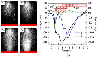
Figure 10: Images of the plasma glow at different time moments at the discharge in the air of atmospheric pressure. (a) C1-C4-channels of the ICCD camera. (b) Waveforms of the discharge voltage (1) and current (2). (3) -displacement current C.dU/dt, where C-a gap capacitance, U-voltage. The time of the channels switching of the ICCD camera is shown by rectangles. The rectangles length corresponds to the exposure duration. The polarity is negative.
It is evident that the streamer has a ball form and its diameter has the dimension of an interelectrode gap (as in the works [36,37]. The diameter of a diffusive plasma column has the maximum dimension after the gap closure by a streamer, and then it begins decreasing. A relatively bright spot on the pin cathode appeared at the diffusive discharge several nanoseconds after the start of a dynamic capacitive current flow through the gap (see the image on the C4 frame). Bright spots in the optimal mode at the negative polarity of the voltage pulse with a small duration (τ0.1–0.7 ≈0.7 ns, τ0.5 ≈4 ns) on the plane anode were absent. There were no local damages of an anode made of Al foil in this mode, as well as in the works in [23,38]. The voltage growth up to 50 kV and more resulted in the spots appearance
Bright spots in the optimal mode at the negative polarity of the voltage pulse with a small duration (τ0.1–0.7 ≈0.7 ns, τ0.5 ≈4 ns) on the plane anode were absent. There were no local damages of an anode made of Al foil in this mode, as well as in the works in [23,38]. The voltage growth up to 50 kV and more resulted in the spots appearance on the anode and its surfaces damage (microcraters formation), and also a spark channel formation.
At the positive polarity of the voltage pulse and the plane cathode in the mode of a diffusive discharge, the bright spots and thereafter erosion tracks on the cathode surface appeared at other equal conditions for a shorter time.
The research was carried out using the setup№ 3 at the interelectrode gap of 9 mm. Used plane electrodes were made of aluminum foil and polished stainless steel. The plane surface of the stainless steel electrode was covered by a layer of graphite. It allowed recording a diffusive discharge influence on the plane electrode erosion more accurately. Besides, a nitrogen circulation through the interelectrode gap was provided at the setup№ 3. It allowed removing the products of the electrode sputtering from the discharge chamber.
After several pulses, appearance of a slight autograph was determined on the graphite layer. The autograph diameter was almost equal to the diameter of the diffusive discharge. Although, the erosion tracks from the microchannels were absent on the autograph. The photo of the autograph that can be distinguished from a non-treated part of the electrode according to a color change of a graphite layer only at the special photo processing and contrast increase is shown in Figure 11a.
As it follows from the experiments, the erosion of a graphite layer was absent at the voltage of a gap breakdown of 31.5 kV for 13 pulses (Figure 11a). A dust particle from the atmospheric air with the diameter of ≈40 μm, which was found on the graphite surface, is shown in the photo (for scale). Note that in this mode only one bright spot was noticeable at the pin cathode.
A wave-like deformation of a surface layer of the graphite and some spots of about 10 μm became visible at the gap breakdown voltage of 39 kV during 10 pulses (Figure 11b). The spots became visible only at the contrast increase of a shot. The reason of their appearance can be the first stage of microcraters formation at the expense of the microchannels or the current density increase on the graphite sections raised a little as a result of deformation. We should note that the microstructure in the diffusive discharge was not recorded with the help of the ICCD camera.
The graphite layer deformation can be explained by the increase of a heat input into the diffusive discharge plasma; that is the plasma was heated strongly and the shock wave influence was amplified.
The photo of a diffusive discharge without a bright spot on the anode is provided in Figure 11d. Similar photos were obtained in the series of 10 pulses and more at the voltage of ≈30 kV. At the same time, a graphite layer was not damaged (Figure 11a). It denotes that the distribution of a current density on the plane anode surface at the diffusive discharge is homogeneous.
The pulses with bright spot on the plane electrode as well as without them were recorded at the voltage breakdown of 39 kV. A heavy damage of a graphite layer (Figure 11c) was observed only at the formation of a bright spot on the anode (Figure 11e). In this case, the place of the electrode erosion corresponded to the place of a bright spot appearance on the plane anode. Some microcraters are well visible in Figure 11c. The minimal dimension of the microcrater was ≈10 μm [see the spot in the center of Figure 11c. The microcraters of 40 μm diameter and more are also visible. It should be noted that the damage character of a graphite layer differs from the damage character of the electrodes made of different metals.
Two jets were recorded in the diffusive discharge in Figure 11e using the digital camera. The first one was with an anode spot, the second one was without it. As we had noted before, the microcraters were recorded on the plane anode only at the existence of a bright spot on it. A graphite layer in the same pulse was not damaged at the arrival place of a second jet on the anode without a bright spot on the anode.
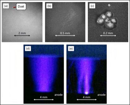
Figure 11: Photos of autographs on the plane anode that was covered by a graphite layer at the influence of the diffusive discharge (a), (b) and a diffusive discharge with a spot on the anode (c), and also photos of a diffusive discharge without a spot on the plane electrode (d) and with a spot (e). Setup № 3. (a)-13 pulses at the amplitude of a voltage pulse U =31.5 kV. (b) -10 pulses at U =39 kV. (c) -1 pulse at U=39 kV. (d) -1 pulse at a diffusive discharge, U = 39kV. (e) -1 pulse at a diffusive discharge with an anode spot, U =39 kV. A pin cathode on the photo (d) and (e) is closed by an insulator.
The bright spots appear much earlier on the surface of a plane cathode at the change of a voltage pulse polarity supplied (from another generator) to the electrode with a small curvature radius (anode). It can be explained by the known fact that the electric field increases on the streamer front [4,39]. The electric field amplifies at the approach of a cathode streamer to the plane electrode near the surface of the electrode; microspikes are heated and exploded on the cathode surface. Thus, the bright electrode spots appear. An effective source of the electron emission from the plane electrode is necessary after the streamer has touched it at the negative polarity of this electrode to keep the current through the gap.
Significant currents from a pin cathode are provided at the expense of the explosive electron emission at the positive polarity of a plane electrode [40]. Besides, bright spots in a stage of a corona discharge can appear on the cathode at high voltage at the expense of the explosive electron emission [41].
The current between the front of the streamer and a plane electrode had been provided by a compressive capacitor charging (dynamic capacitive current [42]) until the gap was closed by a streamer at the positive polarity of a pin electrode as shown in [33,34]. The electron emission from the cathode in this stage is not necessary. However, this mechanism stops working after the streamer front has touched the plane electrode, and the electron emission is necessary from the cathode. The bright spots appearance on the plane electrode and the current keeping through a discharge gap can be explained by the fact that dense plasma appears because of the explosion of microspikes and (or) a breakdown of dielectric films on the plane cathode [43]. Nanoparticles on the surface of a plane cathode can also result in the emission centers appearance [44]. Thus, it is better to apply voltage pulses providing a negative polarity of the electrode with a small curvature radius for soft treatment of a plane electrode. The voltage pulse duration must be shorter at the positive polarity of this electrode.
It follows from the research results at the setup № 1 that a spark discharge as well as a diffusive discharge with bright spots on the plane electrode is microstructured in the wide range of experimental conditions (different materials, pin electrode forms, their polarity). In the first case, a microchannels structure is recorded from the first nanoseconds after the breakdown (from the start of the voltage decrease on the breakdown); in the second case it is recorded in 20- 30 ns after the breakdown start.
The erosion influence on the plane electrode surface recorded at the spark discharge can occur because of the microchannel structure of a discharge that can be the reason of a comparatively high density of the current in the microchannels; and hereby, substantial localization of the heat input on the electrode surface.
It should be noted that a plane electrode (made of aluminum alloy) was not polished between the experiments. That is why, the reason of so fast (3 ns after the voltage delivery) spots appearance on the plane electrode in the spark discharge can be the electric field amplification on the micro inhomogeneities because of the strong erosion of the electrode surface as the result of a multiple discharge effect. The erosion existence was visible. The stated circumstance can be the reason of spots appearance in the diffusive discharge.
The current is about 30 A at the diffusive discharge. However, there was no detailed research of its effect on the surface of a plane electrode on the setup № 1. Thus, it is reasonable to provide other research of diffusive discharges in the geometry pin cathode-plane [45] and a wire (cathode) parallel to the plane [46-48], where the result of the diffusive discharge effect on the plane electrode surface was studied by the method of autographs. A black coating was used in the works for autographs recording. In the works [46-48], the current value in some discharge channels was units of ampere, its duration was from 50 to 100 ns, gaps were up to 10 cm. All channel autographs had a microstructure in the works. Thus, according to the existed experimental data, we can conclude that the microstructure is also formed at the comparatively large interelectrode gaps and low levels of currents. These results differ from the results obtained at the setup № 3. Apparently, this is due to cleaner conditions in the geometry of the experiments at the setup № 3. In particular, gas was pumped through the gap at this setup, which removed metal particles from the flat electrode. As it has been noted above, bright spots were visible on the pin electrode in all the investigated modes. An exception was the corona discharge at low pulse durations and (or) discharge currents.
Let us make some notes regarding the used methods of the microstructure recording and the results obtained using these methods.
Firstly, the later appearance of microchannels on the shadowgraphs of a diffusive discharge (Figure 8) relative to a spark discharge can be the result of its less current. The current cannot provide high gas density gradients recorded by a shadow method for a short time. It should be noted that the pulse duration of the laser used was 6 ns at FWHM. This circumstance can limit the possibility of microchannels recording in the air for a short time (in the initial stages) and/or at the low levels of currents. On the other hand, it is not clear at what time with pulse duration of 6 ns they begin to be recorded.
Secondly, it was impossible to define the stage of the damage start on the setup № 1, though the erosion damage of the plane electrode surface at the spark discharge was observed after every pulse. This is due to the fact that the voltage pulse duration that formed a spark discharge substantially exceeded the duration of the stages of the diffusive glow and electrode spots appearance. At the same time, there was no possibility of the discharge “interruption” on the initial stages to define the presence or absence of the electrode surface damage at this moment.
On the other hand, the absence of damages in the form of microcraters of the plane anode or its covering at the diffusive discharges of small duration without bright anode spots and one cathode spot on the setup № 2 and № 3 indicates that the visible microstructure is absent in the diffusive discharges until the bright spots appear on the electrodes. Thus, it is necessary to continue the research of reasons of the diffusive and spark discharges filamentation and the initial stage of the plane electrodes erosion at their different polarity.
Table 1 shows the characteristics of various discharge modes and the conditions of the surface of the electrodes in these modes.
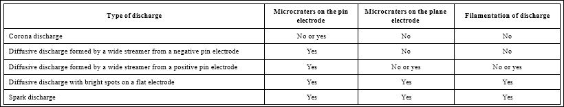
Table 1: The characteristics of various discharge modes and the conditions of the surface of the electrodes in these modes.
At the end of this section we note that studies of the electrode erosion under various discharge regimes were previously mainly studied in relation to the creation of spark gaps [49-52].
Conclusion
The different stages of a pulsed discharge and their conditioned effect on the plane electrode surface were studied at the breakdown of the air of atmospheric pressure in the pin-to-plane gap. The voltage pulses were supplied to the pin electrode with a different profile from the four generators at the variation of an interelectrode distance and also the form, amplitude, and polarity of the voltage pulse. High-speed photo shooting was used for the diagnostics of different discharge stages. The ICCD camera with a minimum frame length of 3 ns and the possibility to record the initial images of a discharge glow for 1 ns and less was also used. The shadowgraph method with a spatial resolution of 5 μm per three pixels was applied. The recording of the discharge erosion effect on the plane electrode surface was realized by the method of autographs.
Four main discharge stages (a corona discharge, diffusive discharge, diffusive discharge with spots (a spot) on the plane electrode, spark discharge) are formed at the use of a high-voltage electrode with a small curvature radius. The discharge stages duration depends on the length of an interelectrode gap, front, duration and amplitude of the voltage pulse, and the shape of a pin electrode. Bright spots or a single spot appear on the electrode with a small curvature radius in the initial stage of a discharge. It also happens at the growth of a voltage pulse amplitude in the stage of a corona discharge. Filamentation of a diffusive and spark discharges is observed at the increase of a voltage pulse length, discharge current, and decrease of an interelectrode gap. It is shown that the plane electrode damage represents an erosion microstructure (a large number of microcraters alternating with the areas without effect) at the large current density and the voltage pulse length.
It is determined that a ball streamer is formed at the gap breakdown at the use of a needle electrode with a small curvature radius. This streamer results in the formation of a diffusive discharge. At nitrogen circulation through the discharge gap (with a negative pin electrode) in the conditions of a diffusive discharge and nanosecond voltage pulses, there are the modes in which we do not observe damage of a plane electrode surface covered by a graphite layer. The further research of physical mechanisms (resulting in the filamentation of diffusive and spark discharges) and dynamics of their influence on the plane electrode surface in different gases and its pressures are planned.
References
- Meek JM, Craggs JD (1953) Electrical breakdown of gases. Oxford: Clarendon Press.
- Raether H (1964) Electron avalanches and breakdown in Wash- ington : Butterworths.
- Lozanskii ED, Firsov OB (1975) Theory of Moscow: Atomizdat.
- Raizer YP (2017) Spark discharge. Routledge.
- Korolev YD, Mesyats GA (1982) Field-Emission and Explosive Processes in Gas Discharges. Nauka.
- Tarasenko VF (2014) Runaway Electrons Preionized Diffuse Discharges. Nova Science.
- Tarasova LV, Khudyakova LN (1970) X rays from pulsed discharges in air. Sov. Phys. Tech. Phys. 14: 1148.
- Kostyrya ID, Skakun VS, Tarasenko VF, Fedenev AV (2004) Optical characteristics of the plasma of a nanosecond atmospheric-pressure volume discharge in a nonuniform electric Tech Phys 49: 987-992.
- Kosarev IN, Starikovskiy AY, Aleksandrov NL (2019) Development of high-voltage nanosecond discharge in strongly non-uniform gas. Plas- ma Sources Science and Technology 28: 15005.
- Tarasenko VF, Baksht EK, Burachenko AG, Lomaev MI, Sorokin DA, et (2010) On the initiation of a spark discharge upon the breakdown of nitrogen and air in a nonuniform electric field. Tech Phys 55: 904-907.
- Tarasenko VF, Baksht EK, Burachenko AG, Erofeev MV, Lomaev MI (2014) Inflections of spark leaders in elevated-pressure nanosecond gas Tech Phys 59: 494-498.
- Tarasenko VF, Baksht EK, Lomaev MI, Rybka DV, Sorokin DA (2013) Transition of a diffuse discharge to a spark at nanosecond breakdown of high-pressure nitrogen and air in a nonuniform electric field. Tech Phys 58: 1115-1121.
- Tarasova LV, Khudyakova LN, Loiko TV, Tsukerman VA (1974) Fast elec- trons and x rays from nanosecond gas discharges at 0.1-760 torr. Sov Phys Tech Phys 19: 351.
- Tarasenko VF, Baksht EK, Beloplotov DV, Burachenko AG, Sorokin DA, et al. (2018) Generation and registration of runaway electron beams during the breakdown of highly overvoltaged gaps filled with dense gas- Journal of Physics D: Applied Physics 51: 424001.
- Mesyats GA, Pedos MS, Rukin SN, Rostov VV, Romanchenko IV, et (2018) Formation of 1.4 MeV runaway electron flows in air using a solid-state generator with 10 MV/ns voltage rise rate. Applied Physics Letters 112: 163501.
- Shao T, Tarasenko VF, Zhang C, Lomaev MI, Sorokin DA, et (2012) Spark discharge formation in an inhomogeneous electric field under conditions of runaway electron generation. Journal of Applied Physics 111: 023304.
- Yatom S, Vekselman V, Gleizer JZ, Krasik YE (2011) Space-and time-re- solved characterization of nanosecond time scale discharge at pressur- ized gas. Journal of Applied Physics 109: 073312.
- Babich LP (2003) High-Energy Phenomena in Electric Discharges in Dense Gases: Theory, Experiment and Natural Phenomena. Future- past, Arlington.
- Perminov AV, Tren’kin AA (2005) Microstructure of the current channels in a nanosecond spark discharge in atmospheric-pressure air in uniform and highly nonuniform electric Technical Physics 50: 1158-1161.
- Tren’kin AA (2019) Erosion Action of a Microstructured Spark Channel on the Surface of a Plane Copper Technical Physics 64: 159- 161.
- Almazova KI, Belonogov AN, Borovkov VV, Gorelov EV, Morozov IV, et (2018) Microstructure of a Spark Discharge in Air in a Point–Plane Gap. Technical Physics 63: 801-805.
- Korenyugin DG, Martsinovsky AM, Orlov KE (2009) Field electron emis- sion from cathode as a possible factor in the transition from a streamer to spark discharge channel. Technical Physics Letters 35: 944.
- Baksht EK, Blinova OM, Erofeev MV, Karelin VI, Ripenko VS, et al. (2016) Dynamics of the spatial structure of pulsed discharges in dense gases in point cathode-plane anode gaps and their erosion effect on the plane electrode surface. Plasma Physics Reports 42: 876-886.
- Almazova KI, Belonogov AN, Borovkov VV, Gorelov EV, Morozov IV, et (2019) Investigation of Spark Discharge Dynamics in an Air-Filled Point–Plane Gap by Shadow Photography. Technical Physics 64: 61-63.
- Tren’kin AA, Almazova KI, Belonogov AN, Borovkov VV, Gorelov EV, et (2019) Dynamics of the Initial Stage of the Spark and Diffuse Dis- charges in Air in a Point–Plane Gap at Different Parameters of the Tip Electrode. Technical Physics 64: 470-474.
- Parkevich EV (2017) The installation to study the prebreakdown stage of a gas discharge by laser probing. Instrum Exp Tech 60: 383-389.
- Parkevich EV, Khirianova AI, Agavonov AV, Tkachenko S, Mingaleev AR, et al. (2018) Anode plasma formation at the initial stage of a nano- second air discharge. Journal of Experimental and Theoretical Physics 126: 422-429.
- Efanov VM, Efanov MV, Komashko AV, Kriklenko AV, Yarin PM, et al. (2010) High-voltage and high-PRF FID pulse In Ultra-Wide- band, Short Pulse Electromagnetics 9, edited by F. Sabath, D. V. Giri, F. Rachidi, and A. Karelin (Springer New York, New York, NY, 2010) pp. 301-305.
- Lomaev MI, Beloplotov DV, Sorokin DA, Tarasenko VF (2016) Spectral and amplitude-time characteristics of radiation of plasma of a repetitive- ly pulsed discharge initiated by runaway electrons. Opt Spectrosc 120: 171-175.
- Korotkov SV, Aristov YV, Kozlov AK, Korotkov DA, Lyublinsky AG, et al. (2012) Installation for air cleaning from organic impurities by plasma formed by barrier discharge of nanosecond duration. Instrum Exp Tech 55: 605-607.
- Shao T, Tarasenko VF, Zhang C, Rybka DV, Kostyrya ID, et al. (2011) Runaway electrons and x-rays from a corona discharge in atmospheric pressure air. New Journal of Physics 13: 113035.
- Tarasenko VF, Baksht EK, Sosnin EA, Burachenko AG, Panarin VA, et al. (2018) Characteristics of a pulse-periodic corona discharge in atmo- spheric air. Plasma Phys Rep 44: 520-532.
- Beloplotov DV, Lomaev MI, Tarasenko VF, Sorokin DA (2018) Measure- ment of the dynamic displacement current as a new method of study of the dynamics of formation of a streamer at a breakdown of gases at a high pressure. JETP Lett 107: 606-611.
- Sorokin DA, Tarasenko VF, Beloplotov DV, Lomaev MI (2019) Features of streamer formation in a sharply non-uniform electric field. Journal of Applied Physics 125: 143301.
- Tarasenko V, Kuznetsov V, Panarin V, Skakun V, Sosnin E (2019) Role of streamers in the formation of a corona discharge in a highly nonuni- form electric field. JETP Lett 110: 85-89.
- Tarasenko VF, Naidis GV, Beloplotov DV, Kostyrya ID, Babaeva NY (2018) Formation of wide streamers during a subnanosecond discharge in atmospheric-pressure air. Plasma Phys Rep 44: 746-753.
- Tarasenko VF, Naidis GV, Beloplotov DV, Lomaev MI, Sorokin DA, et (2018) Streamer breakdown of atmospheric-pressure air in a non-uni- form electric field at high over voltages. Russ Phys J 61: 1135-1142.
- Erofeev MV, Baksht EK, Burachenko AG, Tarasenko VF (2015) Condi- tions for uniform impact of the plasma of a runaway-electron-induced pulsed diffuse discharge on an anode. Tech Phys 60: 1316-1320.
- Pancheshnyi S, Nudnova M, Starikovskii A (2005) Development of a cathode-directed streamer discharge in air at different pressures: Ex- periment and comparison with direct numerical simulation. Phys Rev E 71: 016407.
- Mesyats GA (2013) Ecton mechanism of the cathode spot phenomena in a vacuum arc. IEEE Transactions onPlasma Science 41: 676-694.
- Shao T, Zhang C, Niu Z, Yan P, Tarasenko VF, et al. (2011) Runaway electron preionized diffuse discharges in atmospheric pressure air with a point-to-plane gap in repetitive pulsed Journal of Applied Physics 109: 083306.
- Shao T, Tarasenko VF, Zhang C, Burachenko AG, Rybka DV, et al. (2013) Application of dynamic displacement current for diagnostics of subnanosecond breakdowns in an inhomogeneous electric field. Re- view of Scientific Instruments 84: 053506.
- Andronov A, Budylina E, Shkitun P, Gabdullin P, Gnuchev N, et al. (2018) Characterization of thin carbon films capable of low-field electron Journal of Vacuum Science &Technology B 36: 02C108.
- Kalered E, Brenning N, Pilch I, Caillault L, Minéa T, et (2017) On the work function and the charging of small (r≤ 5 nm) nanoparticles in plas- mas. Physics of Plasmas 24: 013702.
- Rep’ev AG, Repin PB, Pokrovskiĭ VS (2007) Microstructure of the cur- rent channel of an atmospheric-pressure diffuse discharge in a rod- plane air gap. Tech Phys 52: 52-58.
- Buranov SN, Gorokhov VV, Karelin VI, Pavlovskiĭ AI, Repin PB (1991) Wide-aperture source of x-ray radiation for preionization of the large-vol- ume electric-discharge lasers. Soviet Journal of Quantum Electronics 21: 806-808.
- Buranov SN, Gorokhov VV, Karelin VI, Repin PB (1998) The microstruc- ture of the current channels and the runaway of electrons in a high-volt- age diffuse discharges in atmospheric pressure. In Studies of plasma physics, edited by D. Selemir and A.E. Dubinov (RFYaTs-VNIIEF, Sa- rov 39-67.
- Repin PB, Rep’ev AG (2203) In Studies on the Physics of Gas Dis- charge: Collection of Scientific Works, edited by V.D. Selemir and E. Dubinov (RFYaTs-VNIIEF, Sarov 143-172.
- Gray E, Pharney J (1974) Electrode erosion by particle ejection in low-current arcs. Journal of Applied Physics 45: 667-671.
- Donaldson A, Hagler MO, Kristiansen M, Hatfield LL, Ness RM (1985) Modeling of self-breakdown voltage statistics in high-energy spark Journal of Applied Physics 57: 4981-4990.
- Bayer R, Schein J, Schumann M, Mentel J (1997) Optical investigation of the interaction of a dense plasma with cold cathodes in air. IEEE Trans-actions on Plasma Science 25: 1110-1116.
- Rager J, Flaig A, Schneider G, Kaiser T, Soldera F, et (2005) Oxida- tion damage of spark plug electrodes. Advanced Engineering Materials 7: 633-640.
Citation: Almazova KI, Belonogov AN, Beloplotov DV, Borovkov VV, Trenkin AA, et al. (2021) Spatial Structure Formation of Pulsed Discharge in Atmospheric Air and its Erosion Influence on Electrodes in a Pin-to-Plane Gap. J Nanosci Nanomed Nanobio 4: 009.
Copyright: © 2021 Almazova KI, et al. This is an open-access article distributed under the terms of the Creative Commons Attribution License, which permits unrestricted use, distribution, and re- production in any medium, provided the original author and source are credited.